If user experience runs deeper than the user interface, we need a way to talk about an app that isn’t just visual, and that captures behavior in a more fundamental way.
Programmers think in terms of complicated things like objects, callbacks, streams, functionals, and so on. They’re essential for structuring code, but for behavior a much simpler model is effective.
State machines
That model is the state machine. You’ve probably come across state machines, either in a class about the theory of computation, or seeing diagrams like this:
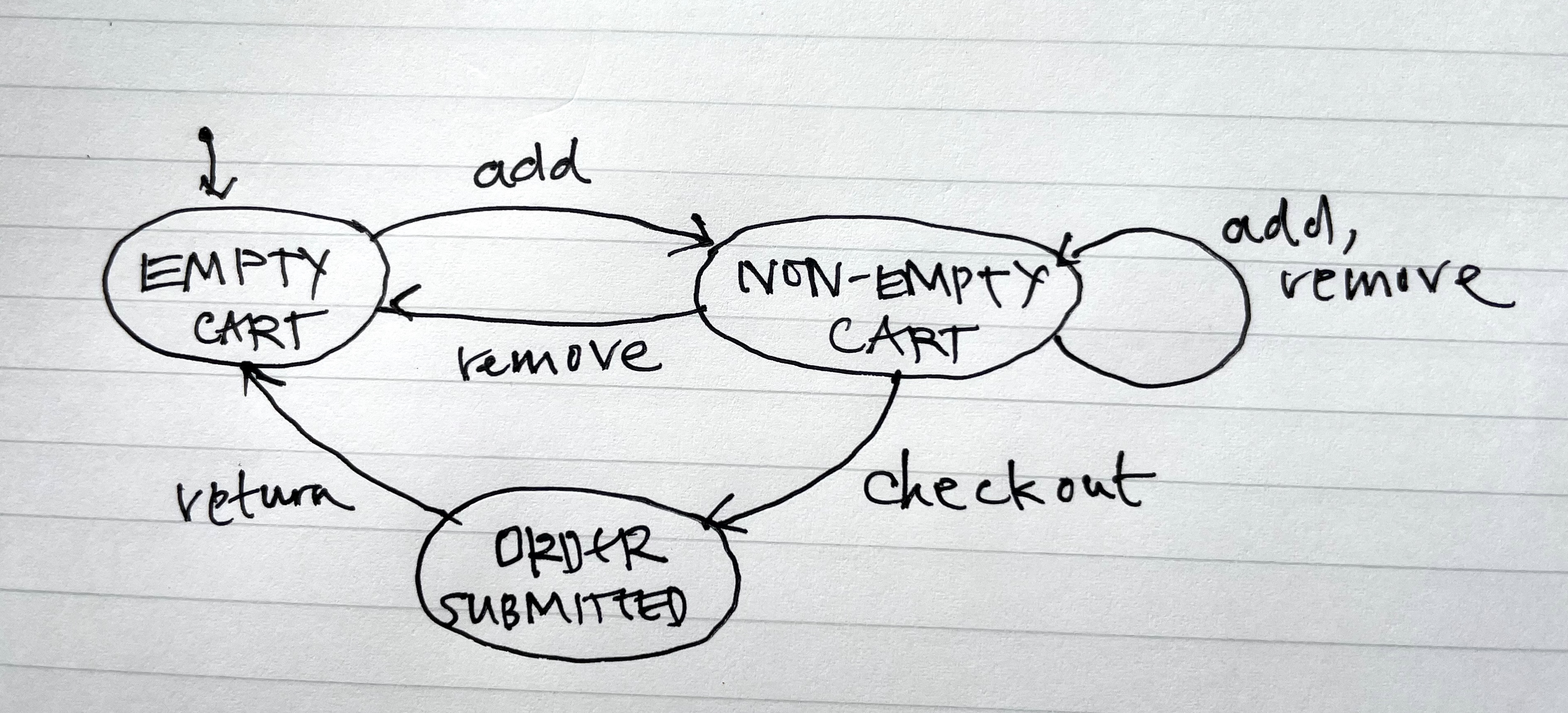
This diagram describes the state machine of a shopping cart. You start with an empty cart; adding an item produces a non-empty cart; then you can add and remove more items; checkout; and then return to the initial state.
Diagrams like this are useful for capturing basic control flow. But they’re not rich enough for modeling behavior, because the number of states must be finite (and small enough to draw!). This diagram doesn’t say that the order you submit when you checkout contains the items you added and didn’t remove. And because individual items aren’t tracked, it needs some non-determinism to model the fact that when you remove an item from a non-empty cart you might end up back with an empty cart (if it was the last item) or you might not (if it wasn’t).
What exactly is a state machine?
To understand exactly what a state machine is, let’s look at an example that’s so simple we can draw it in full. Here’s a rather basic egg timer:
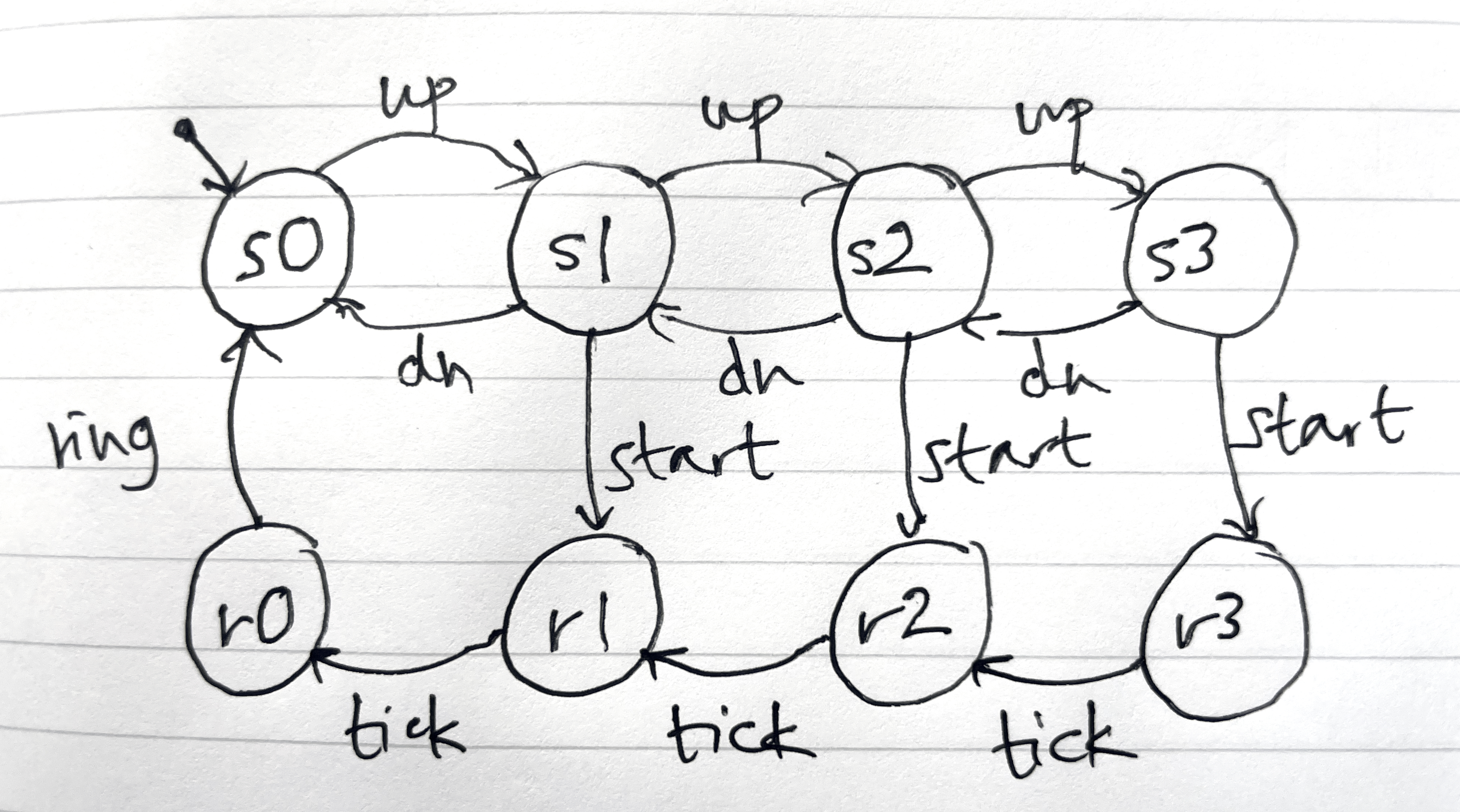
It works like this. You start in the state s0, and then press the up button to increment the timer to s1 corresponding to one minute, s2 for two minutes, or s3 for three minutes; you can press the down button to decrement the timer; and then when you’re ready, you press start and a countdown begins, with r3 meaning running for three minutes, etc; and then when no time is remaining (r0) the timer rings.
We could write down this state machine as a collection of explicit transitions, but to be more succinct we could introduce two separate variables:
time: 0..3
running: bool
and then define an action like this:
up ()
  when not running and time < 3
  time += 1
start ()
  when not running and time > 0
  running := true
This looks more like a program but it’s still a state machine. The states are all the possible environments (that is, bindings of values to variables), and the actions are sets of transitions like (e, a, e’) where e and e’ are the environments before and after and a is the action name. To be pedantic, we might use the term action for the name of an action (and its transitions) and action occurrence for a particular transition.
For example, the action up has three occurrences, of which the first (corresponding to the leftmost arrow in the diagram) is
({time: 0, running: false}, up, {time: 1, running: false})
States
In a more realistic app, the variables won’t have primitive values. Instead, each variable will be a data structure itself. The easiest way to represent such data structures uniformly is to think of them as relations.
The variables representing the state of an online store, for example, might include one holding the number of each item in stock:
stock: Item -> one Number
sets of pending and fulfilled orders for each user:
pending, fulfilled: User -> set Order
a shopping cart for each user:
cart: User -> one Cart
and, for each cart or order, the items it contains:
items: (Cart + Order) -> set Item
The value of each of these variables is a binary relation. The fulfilled variable, for example, is a set of pairs of the form (u, o) where u is a user and o is one of u’s fulfilled orders. Viewed as a table, there’s a separate row for each user and order. So if there are two fulfilled orders for Alice and one for Bob, the table might look like this:
| User | Order |
|---|---|
| Alice | Order_1 |
| Alice | Order_3 |
| Bob | Order_2 |
Actions
Just as the states of a real app are richer, so the actions are a bit richer too. The label of the action includes not only the action name, but often some parameters too.
For example, here’s an action for adding an item to a cart:
add (c: Cart, i: Item)
  when i.stock > 0
  c.items += i
  i.stock -= 1
An example occurrence might be add (c0, i1), meaning an addition of item i1 to cart c0.
The definition of actions is just like it was with the simple egg timer, except now we have to read and write relating values. Here I’m using an Alloy-like notation, in which
c.items += i
means that item i is added to the set associated with the cart c by the items relation. In traditional mathematical notation, it’d be written like this
items' = items U {(c, i)}
where items’ is the value of the items relation after. So this action definition says that when the requested item is in stock, the item is added to the given cart and its inventory count is reduced by one. The when condition is a guard; if it doesn’t hold the action can’t happen. So you can’t add an item to your cart if the item is out of stock.
Removing an item from a cart looks like this:
remove (c: Cart, i: Item)
  when i in c.items
  c.items -= i
  i.stock += 1
When you checkout, a new order is created and made pending, the cart is deleted from the user’s carts, and the order is given the set of items that were in the cart:
checkout (u: User, c: Cart, o: Order)
  new o
  u.pending += o
  c in u.carts
  u.carts -= c
  o.items := c.items
Finally, when an order gets fulfilled, it’s moved from the set of pending orders to the set of fulfilled orders:
fulfill (u: User, o: Order)
  when o in u.pending
  u.pending -= o
  u.fulfilled += o
ER diagrams
An entity-relationship diagram offers a nice way to show the state variables:
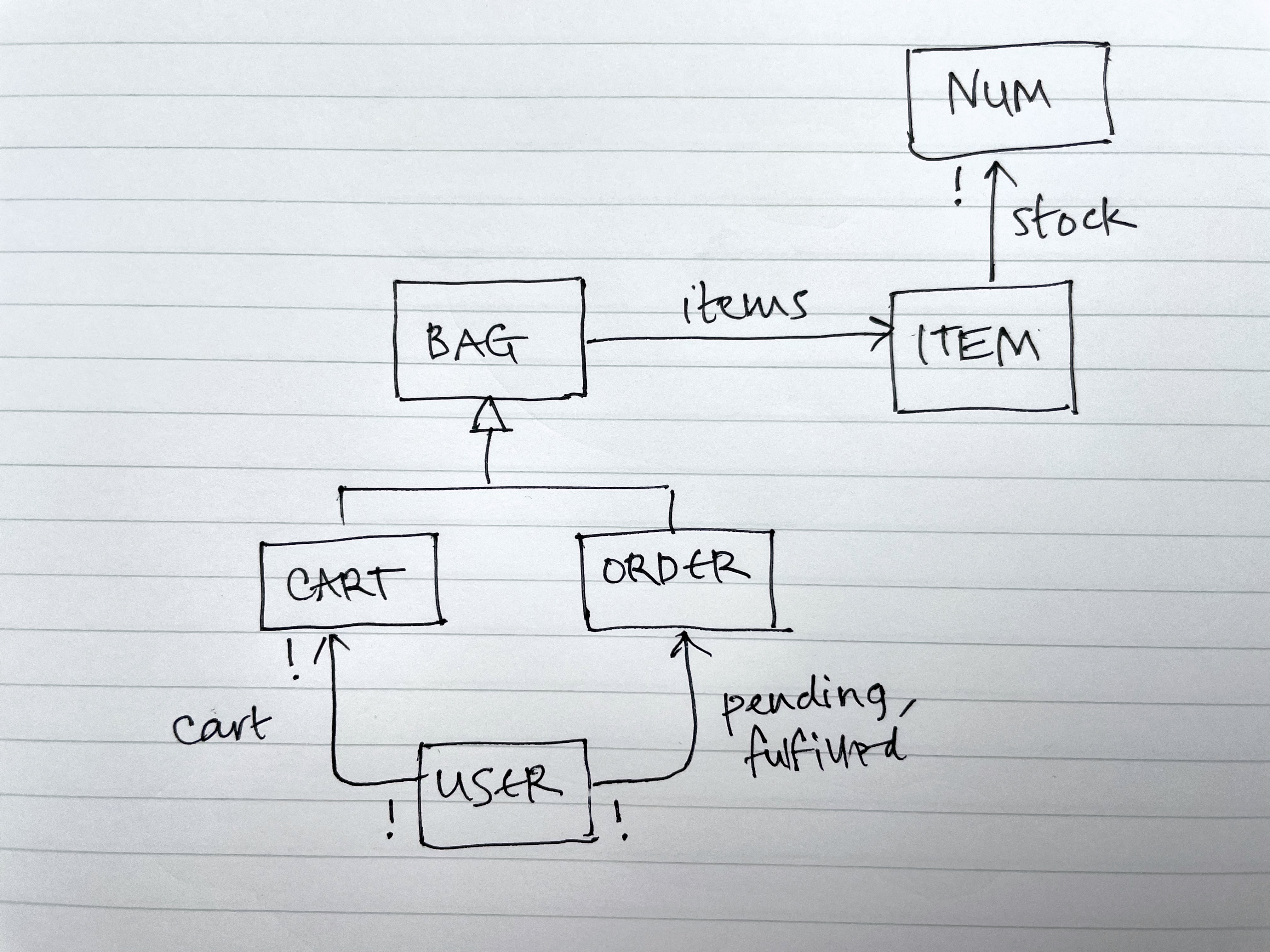
There are a few differences from the textual declarations. I’ve used symbols rather than words for multiplicity (! in place of one, for example). I’ve shown the multiplicity on both ends of a relation: the ! on the source end of the cart arrow says that each cart belongs to one user. You can do both of these textually too. The diagram doesn’t naturally accommodate unions of sets, so for the items relation I introduced a superset called Bag, with each Bag being either a Cart or an Order.
These diagrams are very lightweight and contain lots of information. Working out the details of the state as you the draw the diagram always reveals interesting questions. Can a user have more than one cart, for example? That’s certainly possible for Amazon, because a client-side cart is created before you even log in.
What’s the point?
- UI-independent view. Viewing an app in terms of its state and actions lets you think about its behavior concretely, but without having to consider the details of the user interface. And when you come to design the UI, you can ask yourself how to map the states and actions to UI views and widgets.
- More succinct than use cases. A use case can be useful for describing the details of a workflow, but often a single action will suffice. The checkout action, for example, could encompass all the steps in checking out a shopping cart, and the flow would be better described using wireframes than text. For capturing a fuller journey (that a user adds and removes items from a cart, then checks it out, then the order is fulfilled), I recommend using an operational principle written in terms of actions.
- Path to implementation. It’s easy to extract a relational database schema from the ER diagram. OMT showed how to do this systematically. You can also generate a class hierarchy for an object-oriented approach.
- Small details expose big issues. The biggest advantage of writing down a state machine is that as you work out small details you inevitably encounter questions that expose serious design issues. For example, when I wrote the add action, I had to decide whether it should check the stock of the item, and if so, whether it should decrement it. I decided to do both, which means that (a) you can only add an item that is in stock; and (b) you’re assured that when you checkout, the item you wanted won’t have been taken by someone else. But this convenience for the user comes at a cost for the company, because it means that items will be shown as unavailable when they haven’t yet been paid for. And there will need to be a way to return an item to the inventory if too much time elapses with the cart not being checked out.
Describing a whole app as a single state machine rarely makes sense (unless it’s a very small app). Concepts to the rescue! Just as you can describe an app as a state machine, we’ll see that you can do the same thing for an individual concept. Then an app is just a composition of concepts, and you can define in detail only the concepts that seem tricky or interesting.
Some technical notes
-
History. This kind of state machine model was introduced by the Z Notation in the late 1970s, and became universal in all formal modeling languages (VDM, B, TLA and my own language Alloy).
-
Global state. The state represents the entire global state of the app, frontend and backend. A state machine can describe a distributed system too. Butler Lampson shows how to do this in his course notes on operating system design.
-
Notational nitpicks. The notation I used in the example is mostly from Alloy, with a shorthand for updating a relation. The statement c.items -= i would be written c.items’ = c.items + i in Alloy. There’s a crafty overloading going on in the treatment of the inventory counting: since the stock variable maps each item to exactly one number, I’ve written i.stock += 1 for i.stock’ = plus(i.stock, 1), with the + meaning integer additional and not the set union it usually means in Alloy.
-
Visible state. In many formal methods, the state is assumed to be hidden, and the user’s view of the state is represented by observer actions that produce outputs but don’t update the state. It’s easier to just assume that the state is by default visible to the user, and to describe how and when the user can view the state as part of the user interface mapping.
-
Relations and RDBs. Relations don’t need to be binary. But relations of higher-arity should only be used when there’s a genuine need to relate more than two things: in RDB terms, the relations should be fully normalized. For example, to allow more than one of a given item in a cart or order, we could declare a 3-place relation containing the tuple (c, i, n) when cart c has n copies of item i:
items: (Cart + Order) -> Item -> one Number -
Output actions. Actions can be inputs (initiated by a user) or outputs (initiated by the system). An input action can have output parameters as well as input parameters.
-
Determinism. I prefer all actions to be deterministic. This doesn’t actually prevent the system from making choices that aren’t controlled by the user; it just means that those choices must be exposed in action parameters. For example, an airline reservation system might assign a seat to a passenger with an action whose signature is
assignSeat (p: Passenger, out s: Seat)Thanks to Gordon Cassie for comments on this post which led to several improvements.